Not all voxels along the ray contribute to the rendered image with the same weight. Only some of them belong to the interesting objects, while others can be traversed rapidly or can even be skipped entirely. This capability is called space-leaping and exploits some kind of coherency inherent to the object and/or image space as well as to a sequence of consecutive images.
The macro region based voxel traversal algorithms exploit the object space coherency, i.e., a tendency of object (background) voxels to occupy connected regions of space. In this case, background voxels are gathered into cubic, parallelepipedal or spherical macro regions, which can be skipped at one step thus reducing the number of steps and therefore also the total rendering time. Various schemes for the macro region definition are possible. Some of them are based on hierarchical encoding of the scene space, others define the macro regions directly for the original voxel scene.
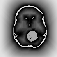
Figure 1: Segmented CT slice of a head with assigned distances.
The CD voxel traversal is based on the assumption that
the chessboard distance to the nearest
object voxel is assigned to each 0-voxel ![]() .
Thus a cubic macro region
.
Thus a cubic macro region ![]() is created around each 0-voxel:
is created around each 0-voxel:
![]()
with its center in ![]() and with side size 2n+1.
In other words, the macro region represents a sphere in
and with side size 2n+1.
In other words, the macro region represents a sphere in ![]() metrics with diameter n.
Since CD is independent of the projection parameters,
it can be calculated and assigned during a preprocessing phase just after
the segmentation.
No extra space is necessary for storage of the distance information,
if we use the originally ``empty'' background voxels.
In this case, in order to distinguish between the object identifier
and the distance, a flag bit should be reserved within each voxel descriptor.
metrics with diameter n.
Since CD is independent of the projection parameters,
it can be calculated and assigned during a preprocessing phase just after
the segmentation.
No extra space is necessary for storage of the distance information,
if we use the originally ``empty'' background voxels.
In this case, in order to distinguish between the object identifier
and the distance, a flag bit should be reserved within each voxel descriptor.
Figure 2: CD algorithm: speeding up the discrete
ray traversal by cubic macro regions
Let us imagine the following situation. The ray is passing in a close vicinity of an object. The step size (and therefore also its speed) is decreasing first, then it reaches its minimum and then it is again increasing. In the last phase, the factor limiting the step size is the distance to the object already passed. This drawback can be overcome by introduction of anisotropic macro regions:
![]()
where
![]()
and
![]()
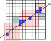
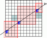
We see that in this case the actual voxel lies in one of the macro region vertices. However, instead of one symmetric macro region, 8 anisotropic macro regions can be assigned to each background voxel. Which of them is loaded to speed-up the traversal depends on the projection vector parameters. Both CD voxel traversal approaches with symmetric and anisotropic macro regions are compared in Figure 3. We see that the additional speed up is obtained by increasing the speed of the rays passing in close vicinity of objects.
| 
|
|---|---|
| (a) | (b) |
Figure 3: Comparison of two CD traversal schemes with
(a) isotropic and (b) anisotropic macro regions.
The anisotropic macro regions can be obtained by a minor change of the original algorithm computing the CD.
![]()
where ![]() ,
and
,
and ![]() is spacing along the axis
is spacing along the axis ![]() .
.
Figure 4: Traversal of a rectilinear grid
by cubic macro regions
| 
|
|---|---|
| (a) | (b) |
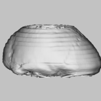
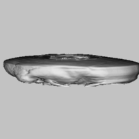
Figure 5: Rendering of a CT data set
(voxel size 0.91x0.45x0.45 mm in the lower part,
5.46x0.45x0.45 mm in the upper part).
(a): correct voxel dimension, (b) voxels treated as cubic.
(Full list of publications)
|
Back to Milos Sramek's home page |
|